EDGE
SUSPENSION

Fabtech’s cutting edge development produces the finest suspension designs for both on and offroad use. Each suspension system is designed to provide an increased ride height for oversized tires while enhancing the suspension performance of the vehicle for offroad use.
Each suspension system design is unique to the vehicle and should be viewed using the Make, Model and Year menu to find the suspension that is right for your use.
SUSPENSION 101
To obtain a better understanding of what each suspension type is and how it functions we have provided the following images and descriptions. These descriptions should be considered general in nature to provide an overview of suspension types to increase product application knowledge. The listed descriptions are derived from stock type suspension design. Fabtech offers product for these suspension types along with hybrid suspensions, such as 4 Link Coilover designs for increased offroad suspension performance.
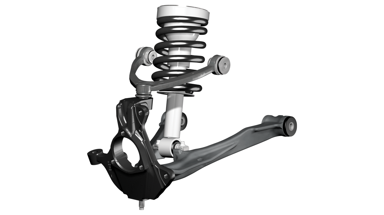
FRONT | A-ARM COILOVER
Coilover independent front suspension (IFS) vehicles incorporate unequal length upper and lower control arms (SLA, “Short Long Arm”) supporting the steering knuckle/spindle using ball joints. This configuration allows for large amounts of articulation while still maintaining proper suspension geometry. To maintain ride height, the coil spring is mounted on the shock absorber, using it as the coil spring mount. The lower control arm supports the load of the vehicle and the upper arm maintains the position of the steering knuckle, allowing the steering system to turn the knuckles left or right. Steering movements are achieved with tie rods positioned to reduce geometry change during suspension travel, also known as Bump Steer.
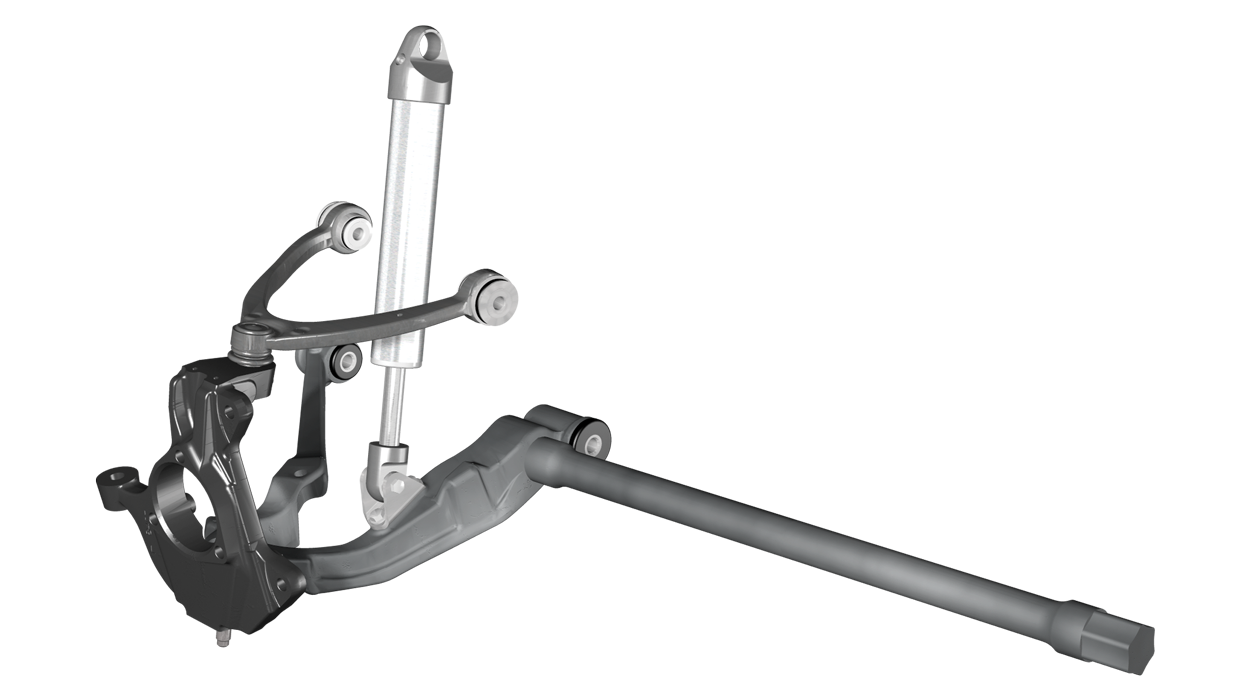
FRONT | A-ARM TORSION BAR
Torsion bar IFS designs incorporate the same SLA configuration, except torsion bars are used in place of coil springs. A torsion bar is a round bar, made of spring steel, mounted longitudinally along the frame rails. The front of the torsion bar attaches to the pivot point of the lower control arm and the other end of the bar is secured to a frame crossmember. Ride height is set by preloading, or twisting, the torsion bars rear mount until the bar supports the weight of the vehicle. As the suspension travels up, the bar is further twisted, increasing the spring force. The ride height of the vehicle can be increased by further preloading the torsion bars, but there are limitations due to suspension travel, CV joint angles on 4 wheel drive models and alignment capabilities.
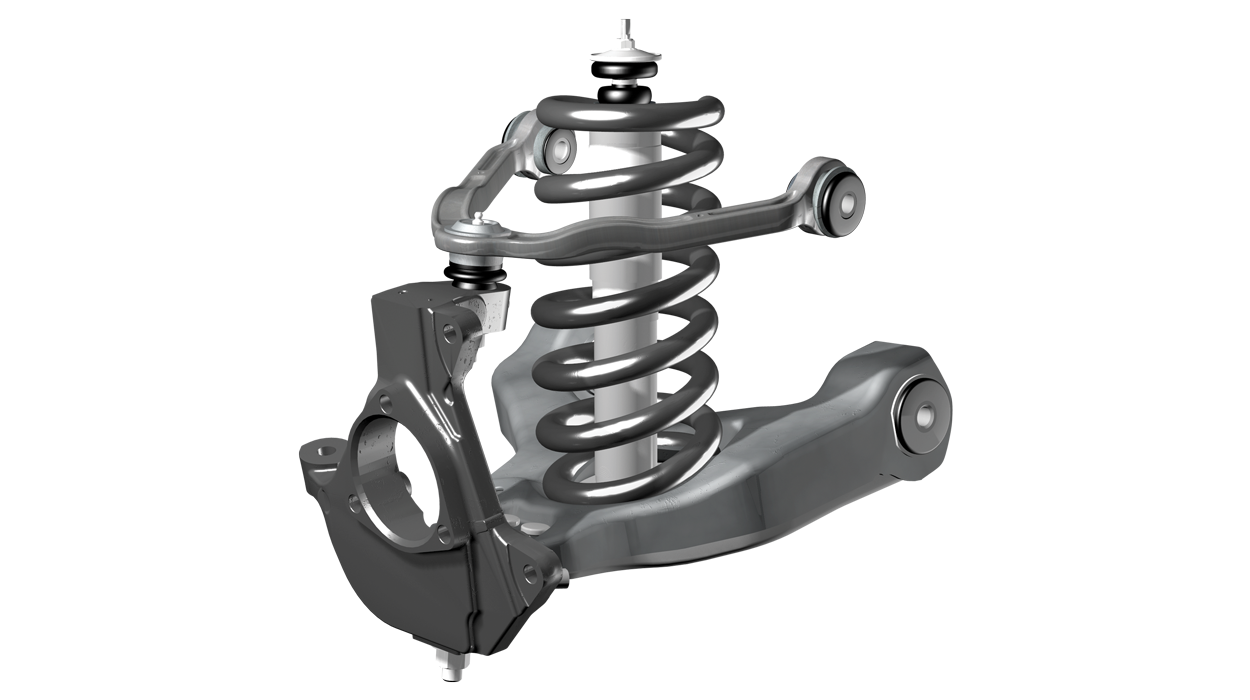
FRONT | A-ARM COIL SPRING
Coil sprung IFS designs also incorporate the SLA configuration, but maintain ride height using a coil spring positioned between the frame and lower control arm. Both sides of the coil spring mount in formed pockets and usually incorporate rubber insolators to reduce noise. The lower control arm supports the load of the vehicle while the upper arm maintains the position of the steering knuckle. This allows the steering system to turn the knuckles left or right. Steering is achieved with tie rods positioned to reduce geometry change during suspension travel, also known as Bump Steer.
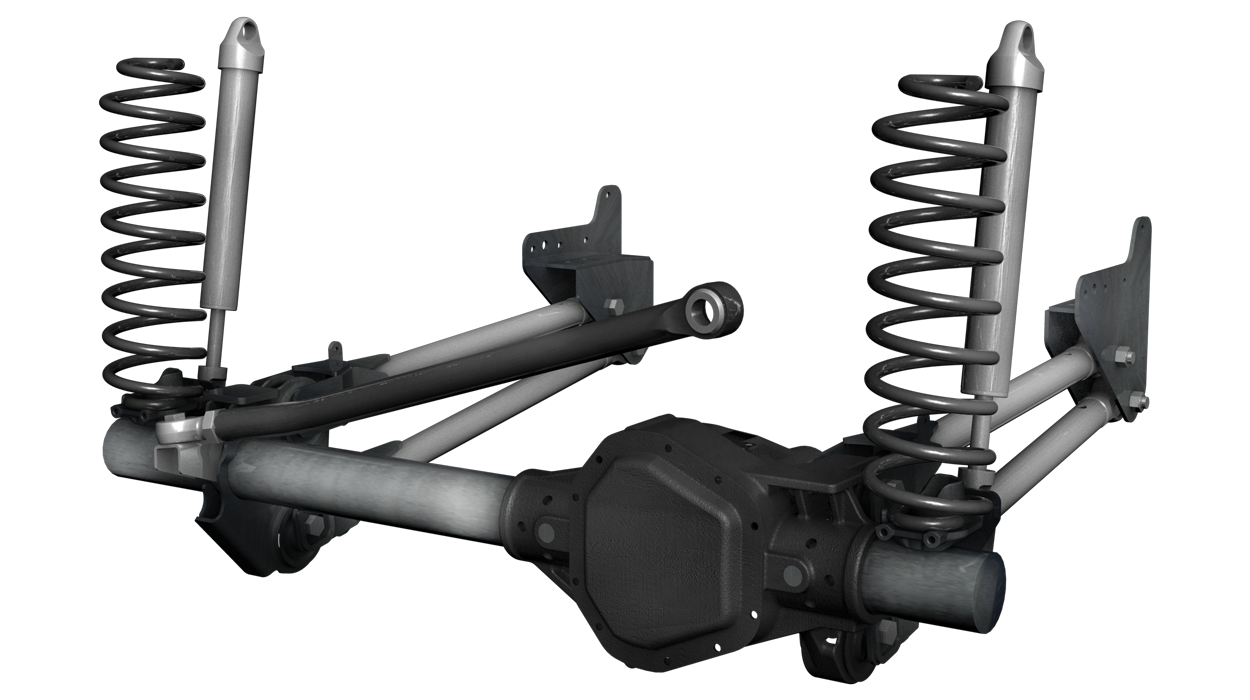
FRONT | RADIUS ARM SOLID AXLE
This design incorporates a solid drive axle using radius arms for front-to-rear positioning of the axle and coil springs to support the vehicle’s weight. The front of the radius arms are attached to the axle housing and run longitudinally along the frame rails, mounting to a single pivot point on the frame. A “track bar”, mounted to the axle housing on the passenger side and the frame-rail on the driver side, keeps the axle centered side-to-side. The track bar and steering draglink geometries are matched to avoid excessive bump steer. The front axle experiences caster (the front to rear tilt of the spindle) change as the suspension cycles, which can have slight adverse effects on steering quality.
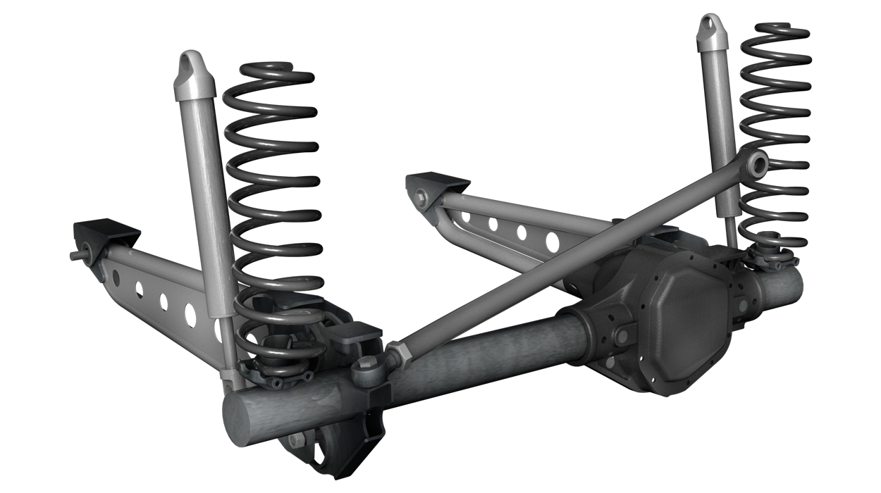
FRONT | 4 LINK SOLID AXLE
The 4 Link Solid Axle design also incorporates a solid drive axle and coil springs, but uses two parallel links per side, instead of radius arms, for front-to-rear positioning of the axle. The 4-link’s arms run parallel from the axle housing, longitudinally along the frame-rails, mounting to pivot points on the frame. This design allows the axle to move in a specific axis reducing the effect on caster and pinion angles. A track bar is also used to keep the axle centered.
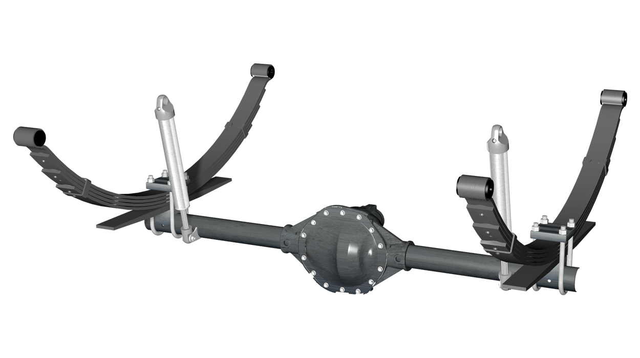
FRONT | LEAF SPRING SOLID AXLE
The Leaf Spring Solid Axle configuration uses a multiple leaf spring-pack, on each side of the axle housing to position the axle and to support the vehicle load. The leaf springs are mounted to a hanger bracket at one end, running longitudinally along the frame-rails, with a pivoting shackle at the opposite end. This simple design locates the axle on a specific axis and supports the weight of the vehicle. A track bar is sometimes used to help center the axle on heavy duty applications.
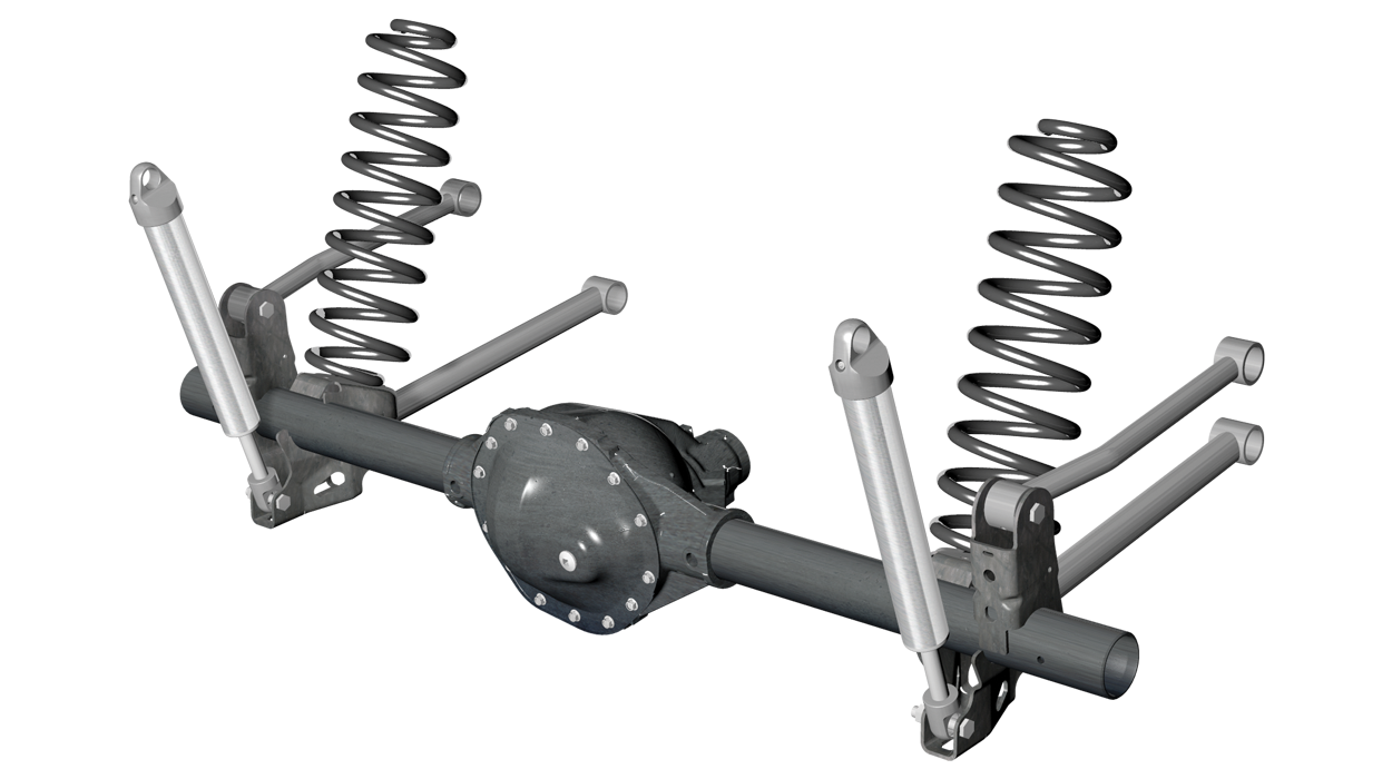
REAR | 4 LINK SOLID AXLE
The 4 Link Solid Axle rear suspension design incorporates a solid drive axle and coil springs, with two parallel links per side for front-to-rear positioning of the axle. The 4-link’s arms run parallel forward from the axle housing, longitudinally along the frame-rails, mounting to pivot points on the frame. A track bar is used on non-triangulated designs to keep the axle centered.
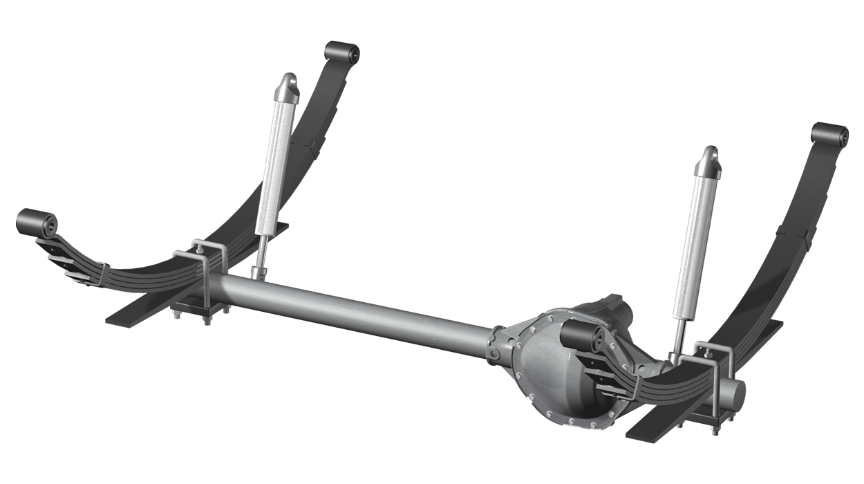
REAR | LEAF SPRING SOLID AXLE
The most popular rear suspension uses a multiple leaf spring-pack, on each side of the axle housing, to position the axle and to support the vehicle load. The leaf springs are mounted to a hanger bracket at one end, running longitudinally along the frame-rails, with a pivoting shackle at the opposite end. The leaf spring design is used in heavy duty application with the addition of overload and helper leafs built into the main spring pack for additional weight capacity.